


 Position:Home >> Products >> Downhole tools
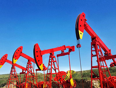
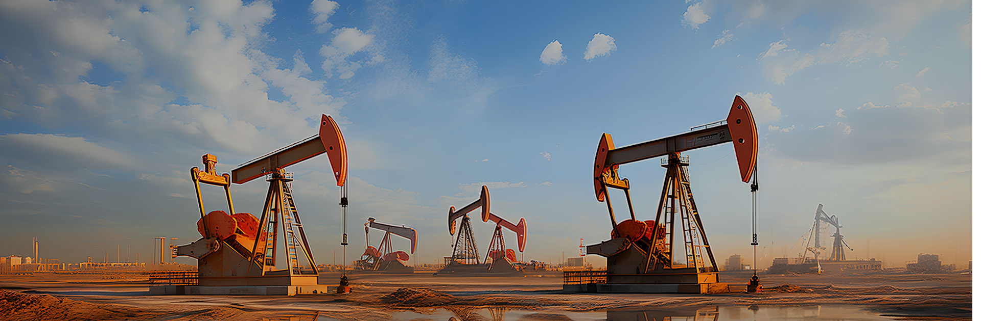
 Product Usage: The product is designed for gas lift oil production.
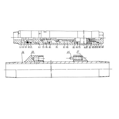
Structure: As shown in the figure , the gas lift device consists of two main parts: one is the gas lift valve part (items 1-23), and the other is the fixed working cylinder part (items 24-27)

Working principle
High pressure gas enters the gas lift valve from the annular space of the tubing and casing, through the side hole of the lower valve body item 6. When the gas pressure is greater than the required pressure of nitrogen gas acting on its effective area inside the bellows, the valve head 8 descends; The gas pushes open the single flow valve 2 from the inner holes of parts 4 and 6 and enters the tubing through the side hole on the tubing pup joint 24. After high-pressure gas enters the tubing, it can lift the liquid out of the ground as required, achieving the purpose of gas lift oil production. The gas lift valve is installed on the outside of the tubing string. When the working parameters of the gas lift valve need to be adjusted, the tubings must be pulled out.
Technical Parameters:
Working pressure | Gas lift valve OD | Tubing pup joint Connection thread |
25MPa | 25mm | 2-7/8TBG |

 ADD:Room 610, Fortune Plaza, Yungang Road, Aviation Economic Zone
 PHONE:+86 153 4632 4105 ; +86 156 1779 7655
TEL:+86 371 85304855

